Introduction
LoRaWAN is commonly used in asynchronous telemetry scenarios: devices emit uplinks periodically or on change,
while downlinks are scheduled (often with delivery constraints). This proposed binding therefore emphasizes
observeproperty/subscribeevent for uplinks and invokeaction/writeproperty
for downlinks. A TD using this LoRaWAN binding conforms if all of the following are true:
- It includes the LoRaWAN binding context in @context (Section 4).
- Any form using LoRaWAN terms follows the constraints in this document (Sections 3–5).
- It validates against the JSON Schema in Appendix (Section A).
LoRaWAN Architecture
LoRaWAN networks use a star-of-stars topology consisting of four logical roles: end node,
gateways, network server, and application servers (plus a Join Server for OTAA activation). Understanding this
separation of concerns is necessary background for the binding defined below.

- End Nodes — sensors and/or actuators that transmit/broadcast LoRa-modulated messages and, depending on device class, open receive windows to accept downlinks. End devices are not paired to a specific gateway, instead any gateway in range can receive the transmission.
- Gateways — receive LoRa messages from any end device in range and forward them transparently to the Network Server over a backhaul (cellular, WiFi, Ethernet, or fiber). Gateways perform no application-level processing and each gateway is registered to exactly one Network Server.
- Network Server (NS) — manages the network: deduplicates uplinks received by multiple gateways, validates message integrity, selects the best gateway for each downlink, runs Adaptive Data Rate (ADR), handles MAC-layer commands, and routes application payloads to the appropriate Application Server.
-
Application Server (AS) — processes application-layer data (decrypted with
AppSKey) and generates downlink application payloads, which it passes to the Network Server for delivery. A network may have multiple Application Servers for different applications. -
Join Server (JS) — handles OTAA device activation, processing Join-request messages and
distributing session keys (
NwkSKeyto the NS,AppSKeyto the AS).
Uplink messages travel from an end device, are received by every gateway in range, and are deduplicated and routed by the Network Server to the correct Application Server. Downlink messages originate at the Application Server, pass through the Network Server — which selects a single best gateway for transmission — and are delivered to the end device only within its receive window.
Structure of a LoRaWAN Uplink Message
A LoRaWAN uplink is built from three nested layers: Phyical Layer, MAC Layer, and Frame Layer. Each layer is
handled by a different component. No single component sees the message in fully decoded form — this is why
a WoT Consumer cannot simply "read" a LoRaWAN device the way it would read an HTTP resource.

-
Physical Layer (PHY) — the LoRa-modulated radio frame:
preamble, PHY header (PHDR), header cyclic redundancy check (PHDR_CRC), and thePHYPayloaditself. This layer is terminated at the Gateway, which demodulates the radio signal and hands the rawPHYPayloadbytes — together with radio metadata such as SNR, frequency, and spreading factor — to the Network Server over the backhaul. The gateway never inspects anything insidePHYPayload. -
MAC Layer —
PHYPayloaddecomposes into MAC Header (MHDR) |MACPayload| Message Integrity Code (MIC). This layer is terminated at the Network Server, which verifies theMICusingNwkSKey, deduplicates copies received via multiple gateways, processes Frame Options (FOpts) MAC commands (e.g., Adaptive Data Rate (ADR)), and tracks Frame Count (FCnt) for replay protection. -
Frame / Application Layer —
MACPayloadcontains the Frame Header (FHDR), Frame Port (FPort), andFRMPayload.FRMPayloadis encrypted withAppSKeywheneverFPort > 0. This layer is terminated at the Application Server, which decryptsFRMPayloadusingAppSKeyto obtain the raw application payload bytes.
Payload Codec
Decrypting FRMPayload does not automatically produce structured application data. — It only
recovers the raw byte string that the LoRaWAN end device originally packed into the uplink. Turning those bytes
into typed values, such as temperature, humidity, battery voltage, alarms, counters, or device status, is the
job of a payload codec, applied immediately after FRMPayload decryption, at the
Application Server.
The codec is usually JavaScript functions not defined by LoRaWAN itself, but depends on the device, vendor, firmware version, and configuration. The codec specification is usually published in a device datasheet, a vendor portal, or an online documentation. It may follow a fixed binary layout, a TLV scheme, Cayenne LPP, a ZCL-based encoding, or a vendor-defined user-configurable format.
In the following, we show some examples of common codec schema.
Fixed Binary Layout with/without branching
In a fixed binary layout, each byte or group of bytes has a predefined meaning.
Example layout:
| Byte Position | Field | Encoding |
|---|---|---|
Byte 0 |
Report type | Unsigned integer |
Byte 1-2 |
Temperature | Signed or unsigned 16-bit integer, big-endian, scale 0.01 °C |
Byte 3-4 |
Unsigned 16-bit integer, big-endian, unit mV | Battery voltage |
Example payload:
01 07 6B 0C CCDecoding result:
0x01: status report0x076B: raw temperature value1899, decoded as18.99 °C0x0CCC: raw battery value3276, decoded as3.276 V
It's worth mentioning, as a decoder output is not standardized, it can return any measurement in any unit, as well as any additional information based on the configuration. So the final structured output could look like this:
{ "reportType": "status", "temperatureC": 18.99, "batteryV": 3.276 }
Branching: Some devices use the first byte, or sometimes the FPort, to indicate
the payload type. The remaining bytes are decoded differently depending on that type. An example is provided in
the following section.
Channel-Type-Value Layout
A Channel-Type-Value format uses a channel identifier and a type identifier before the value. The value length is not explicitly included. Instead, the type determines how many bytes must be read. A common example of this approach is Cayenne Low Power Payload, often called Cayenne LPP.
Generic structure:
[Channel][Type][Value]Example payload:
01 67 00 EA 02 68 7ADecoding:
| Bytes | Meaning | Decoded Value |
|---|---|---|
01 67 00 EA |
Channel 1, type 0x67 = temperature |
Raw value 234, decoded as 23.4 °C |
02 68 7A |
Channel 2, type 0x68 = relative humidity |
Raw value 122, decoded as 61 %RH |
Final structured output could look like this:
{ "channel1": { "type": "temperature", "value": 23.4, "unit": "°C" }, "channel2": { "type": "humidity", "value": 61, "unit": "%RH" } }The advantage of this schema are compactness and interoperability. The disadvantage is that the decoder must know the type table in advance, which offers limited semantics and flexibility.
Type-Length-Value Layout
In a Type-Length-Value format, often abbreviated as TLV, each field contains a type, an explicit length, and then the value bytes.
Generic structure:
[Type][Length][Value]Example payload:
01 02 01 10Example interpretation:
| Part | Value | Meaning |
|---|---|---|
| Type | 0x01 |
Temperature |
| Length | 0x02 |
Two value bytes follow |
| Value | 0x0110 |
Raw value 272, decoded as 27.2 °C |
TLV is more self-describing than a fixed binary layout because each value includes its own length. This makes it easier to add new field types in future firmware versions. However, it has slightly more overhead because every value carries additional metadata.
Vendor-Defined Configurable Layout
Some devices allow users to configure which measurements are sent and in what order. For example, some sensors allow customized extension based on the attached sensors.
Codec JS function example
The following is an example of a JavaScript function for uplink message decoding from the
Netvox: R718A sensor that decodes a fixed binary
layout with branching based on the fPort and the first byte of the payload. The code snippet is
sourced from
TTN device profile repository.
function decodeUplink(input) {
  // Output object — fields are added depending on which fPort and message type is received
  var data = {};

  // fPort identifies the message type.
  // This device uses fPort 6 for sensor data and fPort 7 for command responses.
  switch (input.fPort) {

    case 6: // ── SENSOR DATA PORT ─────────────────────────────────────────────

      // bytes[2] === 0x00 is a special flag meaning this is a VERSION/IDENTITY
      // frame, not a regular sensor reading. Sent once on join or on request.
      if (input.bytes[2] === 0x00)
      {
        // bytes[1]: device type identifier, resolved via a getDeviceName() lookup table not shown here
        data.Device = getDeviceName(input.bytes[1]);

        // bytes[3]: firmware version stored as integer, scaled by 10
        // e.g. 0x0F = 15 → 15/10 = 1.5 (meaning v1.5)
        data.SWver = input.bytes[3] / 10;

        // bytes[4]: hardware revision, raw integer (no scaling)
        data.HWver = input.bytes[4];

        // bytes[5–8]: manufacture date, each byte is one hex pair of the date string.
        // .toString(16) converts the byte to a hex string (e.g. 5 → "5").
        // padLeft(..., 2) zero-pads to 2 chars (e.g. "5" → "05"), ensuring
        // each byte always contributes exactly 2 characters.
        // Concatenated result example: 0x20,0x23,0x12,0x05 → "20231205" (Dec 5, 2023)
        data.Datecode = padLeft(input.bytes[5].toString(16), 2)
                      + padLeft(input.bytes[6].toString(16), 2)
                      + padLeft(input.bytes[7].toString(16), 2)
                      + padLeft(input.bytes[8].toString(16), 2);

        // Return early — version frames contain no sensor readings
        return {
          data: data,
        };
      }

      // ── REGULAR SENSOR FRAME (bytes[2] !== 0x00), sent every 15 minutes at the runtime──────────────────────────

      // bytes[3]: battery voltage.
      // The MSB (0x80 = 10000000) is used as a low-battery flag.
      // & 0x80 isolates that single bit; if it is 1, the battery is low.
      if (input.bytes[3] & 0x80)
      {
        // Mask off the flag bit with & 0x7F (01111111) to get the actual voltage value.
        // Divide by 10 to get volts (e.g. 0x23 = 35 → 35/10 = 3.5 V).
        // Append a warning string so the consumer is immediately aware.
        var tmp_v = input.bytes[3] & 0x7F;
        data.Volt = (tmp_v / 10).toString() + '(low battery)';
      }
      else
        // No low-battery flag — decode voltage directly (e.g. 0x24 = 36 → 3.6 V)
        data.Volt = input.bytes[3] / 10;

      data.Device = getDeviceName(input.bytes[1]);

      // bytes[4–5]: temperature, encoded as a 16-bit big-endian signed integer,
      // scaled by 100 (i.e. 2964 → 29.64 °C, 65436 → −1.00 °C).
      //
      // Negative temperatures are stored in two's complement:
      // the actual range 0x8000–0xFFFF represents −327.68 to −0.01 °C.
      // The most significant bit (MSB) of bytes[4] (checked with & 0x80) acts as the sign bit.
      if (input.bytes[4] & 0x80) // if MSB is set -> negative temperature
      {
        // Reassemble the 16-bit raw value from two bytes (big-endian) via bits shifting:
        // bytes[4] is the high byte → shift left 8 bits,
        // then OR with bytes[5] (low byte) to fill the lower 8 bits.
        // Example: bytes[4]=0xFF, bytes[5]=0x9C → 0xFF9C = 65436
        var tmpval = (input.bytes[4] << 8 | input.bytes[5]);

        // Reverse the two's complement encoding to get the magnitude, then negate.
        // 0x10000 (= 65536) is the 16-bit "clock size"; subtracting gives the distance
        // from zero. Divide by 100 to unscale, multiply by -1 to apply the sign.
        // Example: (65536 − 65436) / 100 * −1 = 100 / 100 * −1 = −1.00 °C
        data.Temp = (0x10000 - tmpval) / 100 * -1;
      }
      else
        // Positive temperature: combine bytes big-endian and unscale directly.
        // Example: bytes[4]=0x0B, bytes[5]=0x94 → 0x0B94 = 2964 → 2964/100 = 29.64 °C
        data.Temp = (input.bytes[4] << 8 | input.bytes[5]) / 100;

      // bytes[6–7]: relative humidity, 16-bit big-endian unsigned, scaled by 100.
      // Humidity is always positive so no sign-bit handling is needed.
      // Example: bytes[6]=0x17, bytes[7]=0x70 → 0x1770 = 6000 → 6000/100 = 60.00 %RH
      data.Humi = (input.bytes[6] << 8 | input.bytes[7]) / 100;
      break;

    case 7: // ── COMMAND RESPONSE PORT ────────────────────────────────────────

      data.Device = getDeviceName(input.bytes[1]);

      // bytes[0] identifies the specific command response type:
      // 0x81 = ACK for a write command (did it succeed?)
      // 0x82 = read-back of the current reporting interval configuration

      if (input.bytes[0] === 0x81)
      {
        // Resolve 0x81 to a human-readable command name via lookup table
        data.Cmd = getCmdId(input.bytes[0]);

        // bytes[2]: 0x00 means the downlink command was applied successfully,
        // any other value means the device rejected or failed to apply it
        data.Status = (input.bytes[2] === 0x00) ? 'Success' : 'Failure';
      }
      else if (input.bytes[0] === 0x82) // event-driven and heartbeat reporting pattern
      {

        data.Cmd = getCmdId(input.bytes[0]);

        // bytes[2–3]: minimum quiet period in seconds.
        // No uplink is sent during this window, even if readings change dramatically.
        // Prevents network flooding from rapid fluctuations.
        // Big-endian 16-bit: bytes[2] is high byte, bytes[3] is low byte.
        data.MinTime = (input.bytes[2] << 8 | input.bytes[3]);

        // bytes[4–5]: maximum heartbeat interval in seconds.
        // The device MUST send an uplink by this deadline even if nothing changed.
        // Allows the server to detect a lost/dead device if no packet arrives in time.
        data.MaxTime = (input.bytes[4] << 8 | input.bytes[5]);

        // bytes[6]: voltage change threshold that triggers an early uplink.
        // Scaled by 10 → e.g. 0x03 = 3 → 0.3 V drop triggers a send.
        data.BatteryChange = input.bytes[6] / 10;

        // bytes[7–8]: temperature change threshold in °C.
        // Big-endian 16-bit, scaled by 100 → e.g. 0x0032 = 50 → 0.50 °C triggers a send.
        data.TempChange = (input.bytes[7] << 8 | input.bytes[8]) / 100;

        // bytes[9–10]: humidity change threshold in %RH.
        // Big-endian 16-bit, scaled by 100 → e.g. 0x01F4 = 500 → 5.00 %RH triggers a send.
        data.HumiChange = (input.bytes[9] << 8 | input.bytes[10]) / 100;
      }
      break;

    default:
      // Any fPort not handled above is unexpected — return a descriptive error
      // so the LNS or WoT Consumer can flag it for investigation.
      return {
        errors: ['unknown FPort'],
      };
  }

  // Return the decoded fields for all non-error, non-early-return paths
  return {
    data: data,
  };
}
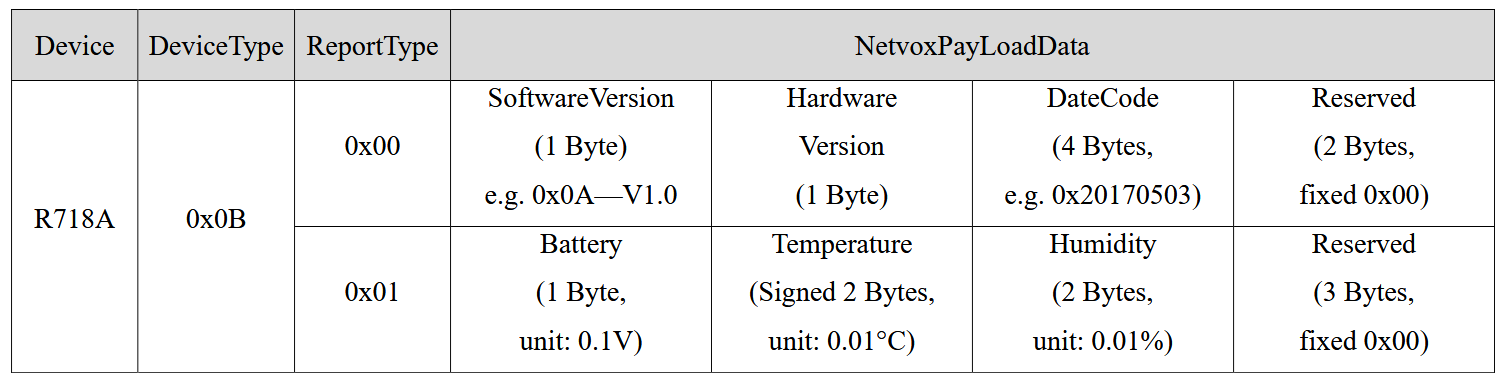
Based on the device datasheet, the following
table shows the meaning of each byte in the payload. For FPort 0x06, the following table applies:
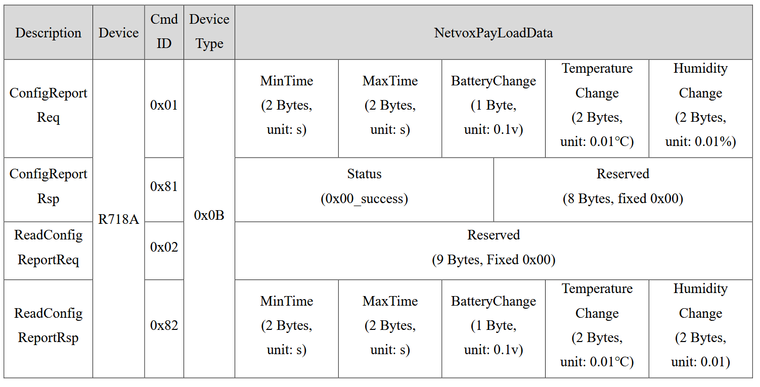
For FPort 0x07, the following table applies:
So an example message "010b01240b2d0bef000000" can be decoded as follows:
| Byte(s) | Hex Value | Field | Description / Calculation |
|---|---|---|---|
| 1st byte | 01 | Version | Version value |
| 2nd byte | 0B | DeviceType | 0x0B - R718A |
| 3rd byte | 01 | ReportType | Report type value |
| 4th byte | 24 | Battery | 3.6V; 24(Hex) = 36(Dec), 36 x 0.1V = 3.6V |
| 5th - 6th byte | 0B2D | Temperature | 28.61°C; 0B2D(Hex) = 2861(Dec), 2861 x 0.01 = 28.61°C |
| 7th - 8th byte | 0BEF | Humidity | 30.55%; 0BEF(Hex) = 3055(Dec), 3055 x 0.01 = 30.55% |
| 9th - 11th byte | 000000 | Reserved | Reserved bytes |